
When people first witness a 3D-printed structure rising from the ground, the most common question — beyond sheer amazement — is: “How does this machine actually work?”
Unlike a desktop FDM plastic printer, a commercial-grade 3D concrete printer (3DCP) capable of reliably producing structural building components is a highly integrated system that fuses mechanical engineering, materials science, motion control, and industrial software. In this article, we deconstruct a real commercial 3DCP system — module by module — and explain what each one does and why it matters.
1. Motion System — The Skeleton & Joints
The motion system is the physical backbone of any 3D concrete printer — it defines the build envelope, accuracy, and degrees of freedom.
Three dominant technical architectures define the commercial landscape today:
1.1 Gantry System
The gantry architecture inherits the proven framework of CNC machining centers, achieving spatial motion through X/Y/Z linear guideways. Its chief advantages are scale, rigidity, and modular extensibility.
| Parameter | Typical Value | Source |
|---|---|---|
| Max Print Envelope | 10m (L) × 6m (W) × 3.6m (H) — extensible to 13.5m × 9m (COBOD) | CCCC / COBOD BOD2 |
| Max Print Speed | 0.5 m/s — industry maximum ~1.0 m/s (COBOD BOD2) | CCCC / COBOD |
| Rated Repeatability (static) | ±0.2 mm — real-world accuracy typically ±1–2 mm under thermal/structural deflection | CCCC / Engineering judgment |
| Rated Payload | 100 kg | CCCC |
| Axes | 5-axis (moving-column design) | CCCC |
| Best For | High-volume, large-scale standardized components: wall panels, municipal elements, signage blocks |
Case Study: CCCC First Highway Consultants’ large-scale 5-axis gantry system has successfully broken through the technical barriers of large-component additive manufacturing, supporting 24/7 uninterrupted production.
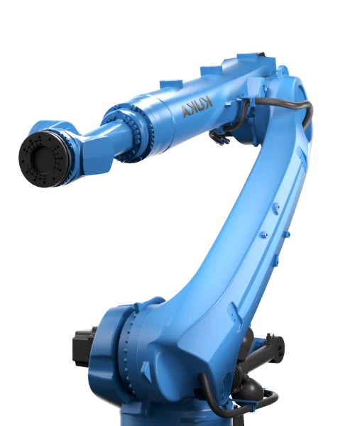
1.2 Robotic Arm System
Robotic arm systems use industrial robots — typically 6-axis or 7-axis collaborative robots — as the kinematic platform. The defining advantage is multi-axis dexterity: the end-effector can tilt at arbitrary angles, enabling the printing of cantilevers, twisted geometries, and doubly curved surfaces.
| Parameter | Typical Value | Source |
|---|---|---|
| Max Reach | 2.7 m | KUKA KR 120 R2700 |
| Repeatability | ±0.06 mm (ISO 9283) | KUKA / CCCC |
| Rated Payload | 120 kg | KUKA / CCCC |
| External Axis | 8 m, extending single-direction build to 6 m | CCCC |
| Print Speed | 0.3–0.5 m/s | CCCC |
| Best For | Complex geometries, twisted cantilever columns, freeform surfaces |
1.3 Mobile Crawler Robots
An emerging frontier: integrating the entire printing system onto a crawler chassis or AGV platform for true in-situ printing. The machine can move freely across the construction site, completely decoupled from fixed gantry dimensions.
AiUltraprod has been at the forefront of this approach, combining proprietary path-planning algorithms with mobile robotics to achieve “print-as-you-go” operation — the robot autonomously navigates to the printing position and executes construction tasks on-site.
2. Feeding & Mixing System — The Digestive System
Concrete is not thermoplastic filament — its rheological behavior changes dramatically with time, temperature, and humidity. This makes the feeding and mixing system one of the highest-barrier modules in any commercial 3DCP setup.
2.1 Dry-Mix Silo
Commercial systems typically feature large-capacity silos (several hundred kilograms to multiple tonnes) storing pre-mixed dry mortar or proprietary printable formulations. Requirements include: moisture-proofing, anti-clumping design, and precision continuous-metering equipment.
2.2 Continuous Mixing System
Dry powder, water, and admixtures must be thoroughly mixed before entering the pumping system. Commercial machines commonly use twin-shaft continuous mixers or helical forced mixers. The critical challenge: mixing rate must be synchronized in real time with pumping rate to prevent premature setting, segregation, or inconsistent water content within the delivery pipeline.
2.3 Pumping System
This is the heart of the entire printing process.
Commercial 3DCP systems widely adopt progressive cavity (screw) pumps — either single-screw or twin-screw — which achieve stable volumetric conveyance through rotor rotation within a stator cavity. Compared to traditional concrete piston pumps, screw pumps offer inherently low pulsation and continuous, uniform flow — a decisive advantage for the extreme consistency demands of additive manufacturing.
| Key Metric | Typical Range | Notes |
|---|---|---|
| Max Pumping Pressure | 2–8 MPa (screw pump); up to 10 MPa for long-distance / high-viscosity | 20 MPa range is for traditional piston pumps only |
| Flow Rate Range | 5–50 L/min, continuously variable | Covers small-nozzle low-speed to large-nozzle high-speed regimes |
| Pulsation Control | Screw pumps inherently low-pulsation; supplemented by dampeners | Significantly superior to piston pump alternatives |
3. Print Head & Extrusion Module — The Skilled Hand
The print head is the terminal actuator across all kinematic architectures — it directly governs print quality, interlayer bond strength, and surface finish.
Commercial print heads have undergone four major generational iterations:
| Generation | Key Feature | Limitation |
|---|---|---|
| Gen 1 | Fixed circular nozzle | Poor quality at path discontinuities |
| Gen 2 | Rotatable, rectangular orifice | Still affected by pump stability |
| Gen 3 | Print-head-integrated auger re-compression | — |
| Gen 4/5 | Telescoping compensation, multi-axis rotation, adjustable rectangular cross-section + path-fitting algorithms | — |
Third-generation auger re-compression is the current mainstream configuration for commercial-grade systems. By integrating a helical pressurization mechanism inside the print head itself, the material receives a secondary compaction step, resulting in denser extrudate and markedly stronger interlayer bonding.
Additional key technical parameters:
| Parameter | Range | Notes |
|---|---|---|
| Nozzle Diameter | Typically 20–50 mm; large systems up to 80–100 mm | COBOD BOD2 supports 30–100 mm layer width |
| Extrusion Rate Control | Real-time synchronization with motion velocity | Ensures uniform layer width |
| Auto-Cleaning & Curing | Standard on commercial systems | Prevents clogging from hardened material |
4. Control System — The Brain & Neural Network
If the mechanical system determines whether the machine can move at all, the control system determines whether it can print well.
A commercial-grade control architecture operates across three layers:
4.1 Motion Control Layer
Responsible for executing G-code trajectory commands and driving servo motors or robotic joints. Commercial systems commonly employ industrial-grade motion controllers (GoogolTech, Beckhoff, Siemens) or dedicated robot controllers (KUKA KRC, ABB IRC5) for multi-axis interpolation, acceleration smoothing (jerk-limited S-curve), and look-ahead path fitting.
Servo-drive current-loop response operates in the microsecond domain; the system-level PLC/IPC process-control closed-loop targets ≤100 ms.
4.2 Process Control Layer
This is what fundamentally separates a commercial-grade machine from a lab prototype.
The process control layer must coordinate multiple subsystems in real time:
- Synchronization of pumping speed and motion velocity
- Matching material flow rate to layer height
- Adaptive adjustment of print-head orientation to path curvature
- Material-level monitoring and run-out early warning
- Ambient temperature/humidity monitoring and parameter compensation
4.3 Software & Data Layer
| Subsystem | Function |
|---|---|
| Slicing Software | 3D model → executable print path; supports freeform surface slicing, support generation, path optimization |
| SCADA Monitoring & Data Acquisition | Multi-dimensional real-time monitoring: print progress, machine status, material consumption |
| Digital Twin | Advanced systems integrate 3D visualization for “what you see is what you get” remote monitoring and interaction |
Verified Case Data: After CCCC First Highway Consultants deployed its integrated hardware-software intelligent control system, operators were reduced from 4 to 1 (a 75% reduction), CNC adoption for critical equipment reached 100%, and quality loss rate dropped by approximately 20%. The system was rated as internationally leading in 2022.
5. Material System — More Than Just “Concrete”
Commercial-grade 3DCP places rheological demands on materials that far exceed those of traditional cast-in-place concrete. A viable printable formulation must simultaneously satisfy three core performance criteria:
5.1 Pumpability
The material must flow smoothly through the delivery pipeline without clogging. Key parameters:
- Aggregate size: fine formulation typically ≤2 mm; coarse recipes up to 8–10 mm (COBOD BOD2 accepts ≤10 mm)
- Rheology: static yield stress 200–2,000 Pa; Bingham plastic viscosity 20–80 Pa·s
- Thixotropy: thinning under shear for easy pumping, then rapidly rebuilding structure at rest
5.2 Extrudability
After extrusion, the material must hold its shape under gravity without slumping. This demands a precise balance between yield stress and plastic viscosity.
5.3 Buildability
When fresh layers are deposited on top of existing ones, the lower layers must not undergo plastic deformation. Commercial systems typically demand that the material develop sufficient green strength to support subsequent layers within 3–10 minutes — a metric known as structuration rate. This is distinct from chemical “initial setting” (typically 30–120 minutes) and refers specifically to the rapid build-up of early-age standing strength.
6. Auxiliary & Safety Systems
A commercial system requires a suite of auxiliary subsystems for operational stability and occupational safety:
| System | Function |
|---|---|
| Calibration & Leveling | Auto-leveling and zero-point calibration before each print |
| Safety Fencing & Light Curtains | Prevent personnel from entering the motion zone (ISO 10218 industrial robot safety) |
| Multi-tier Emergency Stop | Hardware e-stop buttons + remote shutdown capability |
| Dust Management | Dust collection during dry-mix handling and pumping |
| Video Surveillance | Remote real-time machine monitoring |
7. Software Ecosystem — The Digital Bridge from Design to Print
A standalone printer has limited value. What truly unlocks commercial potential is a complete software ecosystem.
AiUltraprod’s intelligent cloud service platform embodies this vision — delivering an end-to-end digital chain spanning demand interaction, design generation, process validation, and production delivery:
| Feature | Description |
|---|---|
| Conversational Design | Natural-language input → conceptual design generation |
| AI Process Validation | Auto-checks 10+ manufacturability constraints (overhang angle, material feasibility, etc.) |
| Template Library | 30+ standard templates, AI match rate 0.92 (manufacturer-claimed) |
| Delivery Tracking & Sync | Real-time equipment-hour sync; component-level production progress tracking |
Conclusion
A commercial-grade 3D concrete printer is far more than a “giant hot-glue gun.” It is a precision-engineered system that integrates mechanical structures, fluid delivery, motion control, materials science, and industrial software. No module is simply bolted on — each must be refined and iterated through sustained engineering practice.
From gantries to robotic arms, from crawler robots to intelligent cloud platforms — 3D concrete printing is transitioning from “can it print?” to “can it print well?” AiUltraprod remains committed to lowering the barrier to entry for this technology, empowering more designers, engineers, and project stakeholders to harness the power of digital construction — starting from a single conversation, turning architecture into reality.