
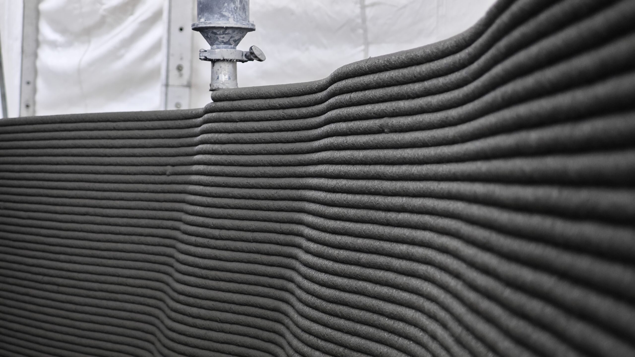
If 3D‑printed concrete has a “fingerprint”, it must be its layer lines.Stretching horizontally across the exterior walls of every printed building, these textures can be as coarse as rock strata or as delicate as wood grain. They stand as the most distinctive visual hallmark of this technology, yet have long sparked debate. Enthusiasts call it “layer‑accumulation aesthetics”, while critics dismiss it as marks of shoddy workmanship.
So the question arises: can layer lines be controlled, and to what extent?
This article unpacks layer lines from four dimensions: material, process, path planning and post‑processing.
I. Where Do Layer Lines Come From? Understanding the Nature of Layer‑by‑Layer Deposition
To control layer lines, one must first understand them. Rather than a pure defect, they are a physical inevitability of extrusion‑based additive manufacturing (the FDM principle):
- A nozzle extrudes flat concrete filaments and lays them onto a substrate following a planned path.
- Before the upper layer fully hardens, the subsequent layer is deposited on top of it.
- Self‑weight of the upper layer induces slight compressive deformation in the top of the lower layer, forming an interface between the two.
- After concrete hardens, minor depressions at interlayer interfaces and rounded transitions along filament edges together form the visually observable “layer lines”.
In short: layer lines equal interface traces from layered deposition plus material‑induced deformation. As long as the process works by extruding strips and stacking layers, layer lines cannot be completely eliminated. The real question is whether we can make them appear as intended by design.
Three physical quantities govern how visible layer lines are:
| Physical Quantity | Definition | Impact on Layer Lines |
| Layer Height | Vertical distance between centres of adjacent layers | Larger layer height produces broader, more prominent layer lines |
| Layer Width / Extrusion Cross‑section | Width and cross‑sectional shape of concrete filaments | More regular cross‑sections yield smoother side edges |
| Inter‑layer Settlement | Deformation of the lower layer under loading from the layer above | More uniform settlement creates more consistent layer lines |
II. Six “Control Knobs” for Regulating Layer Lines
Layer lines are not random occurrences but outputs of a parametric system. Engineers can tune them along six dimensions:
Knob 1: Material Rheology — the Innate Traits of Layer Lines
Material performance fundamentally determines whether fine layer lines can be achieved in printed concrete.
- Thixotropy: Materials thin under shear (facilitating extrusion) and thicken at rest (supporting overlying weight). Faster thixotropic recovery yields cleaner interlayer interfaces.
- Yield Stress: Governs whether freshly extruded filaments can retain their shape. Insufficient yield stress allows upper layers to crush lower ones, turning sharp layer lines into smudged marks.
- Open Time (Build Window): The period during which material remains workable. Too short a window causes cold joints between layers — a major hazard for layer‑line control. If printing pauses beyond this window (sometimes only a dozen minutes for certain materials), a structurally weakened construction joint forms at the resumption point.
- Aggregate Size and Gradation: Maximum coarse‑aggregate size is generally limited to 1/5 of the nozzle diameter. Exceeding this threshold results in ragged filament edges and fragmented layer lines.
Knob 2: Printing Parameters — Refining Layer Lines Post‑Formation
- Layer Height: Industry empirical practice sets layer height at 0.6‑0.8 times the layer width. Values below 0.6 trigger excessive overlap and material squeezing‑out; values above 0.8 lead to insufficient inter‑layer overlap and weakened interfacial bonding.
- Matching Print Speed and Extrusion Rate: This poses one of the strictest precision challenges. Excess speed causes filament stringing; insufficient speed causes material build‑up. Only precise matching between extruded volume and travel speed yields well‑defined rectangular or trapezoidal cross‑sections.
- Path Spacing (Line‑to‑line Distance): Centre‑to‑centre distance between adjacent filaments, directly governing the rhythm of surface undulation.
Knob 3: Path Planning — Layout Design for Layer Lines
Layer‑line quality is as much a mathematical problem as a material one. Identical nozzles and materials can produce vastly different layer patterns depending on tool‑path strategies:
- Layer lines tend to break down at corners; appropriately sized corner radii prevent distorted layer textures.
- Denser pathing for exterior surfaces paired with sparse internal infill achieves fine exteriors with coarser internal structures.
- Starting‑point offset and contour‑offset strategies eliminate vertical seam lines caused by aligned layer‑to‑layer joints.
Knob 4: Timing Control — the Metronome of Layer‑Line Formation
- Inter‑layer Dwell Time: Stable pause duration between successive layers is essential. Too short a dwell allows unhardened upper layers to sag; too long creates cold inter‑layer joints.
- Consistent Printing Rhythm: Extrusion compensation for equipment acceleration, deceleration and direction changes determines layer‑line uniformity.
Knob 5: Environmental Factors — External Disturbances
Wind, temperature and humidity alter material moisture‑loss and setting kinetics. In outdoor printing, surfaces exposed to sunlight may develop different layer‑line appearances compared with shaded sides. Best practice includes local climate control around the print zone or formulating materials with improved environmental robustness.
Knob 6: Post‑processing — the Final Step for Layer‑line Performance
Print completion marks only roughly 60 % of the finished surface. For applications demanding high surface quality:
- Sanding: Blunts sharp ridges of layer lines.
- Spraying polymer‑modified mortar or coloured protective coatings: Seals surface pores, unifies visual appearance and enhances durability.
- Exposed‑aggregate finishing / Acid etching: Converts layer lines into rugged decorative textures.
III. Beyond Aesthetics: Mechanical Trade‑offs behind Layer Lines
Layer lines are not merely cosmetic; they affect structural strength.
3D‑printed‑concrete components are inherently anisotropic. Strength in the in‑plane (horizontal) direction is generally satisfactory, yet inter‑layer (cross‑interface) bonding strength typically reaches only 60 %‑80 % of bulk strength. Inter‑layer interfaces concentrate pores and weak planes, acting as prime sites for crack initiation.
This means adjustments that smooth and refine layer lines may simultaneously alter structural behaviour:
- Reducing layer height → more interfaces → anisotropic performance requires re‑evaluation.
- Increasing flowability → smoother layer appearance → higher risk of structural collapse and reduced inter‑layer mechanical interlocking.
- Adjusting path density → finer surface finish → altered internal density distribution, requiring re‑verification of topological load‑bearing paths.
For this reason, professional teams do not pursue smoothness for its own sake. Layer‑line control is a multi‑objective optimisation balancing visual effect, structural performance, cost and efficiency — a key distinction between real‑world 3D‑printed buildings and small printed model prototypes.
IV. From Hiding to Designing Layer Lines: Three Aesthetic Approaches
Re‑framed, layer lines can become a design asset. Three distinct approaches are emerging across the industry:
- Smooth Aesthetic (Concealing Layer Lines): Suited for residential and commercial projects aligned with mainstream visual expectations. Post‑processing erases visible layer lines so printed buildings resemble conventionally constructed counterparts, lowering market‑adoption barriers.
- Textured Aesthetic (Retaining Layer Lines): Treats layer lines as intentional decorative language — concrete’s “growth rings”. Tuning layer‑height rhythms and tool‑paths yields gradients, patterns and parametric textures. Museums, exhibition pavilions and landscape structures represent ideal use‑cases.
- Structural Aesthetic (Layer Lines as Part of Structure): Aligns layer‑line orientations with load paths. Layer lines are no longer side‑effects but direct outcomes of topological optimisation. Every visible texture traces lines of force transfer.
V. AiUltraprod’s Solution: Integrated Control of Materials, Hardware and Algorithms
At AiUltraprod, we recognise layer‑line quality cannot be achieved by tuning single parameters. Instead, it represents a system‑level output from the integrated triad: materials‑hardware‑algorithms.
- Materials: Our proprietary printable ink system uses rheological modulation to render build window and thixotropic‑recovery performance design‑tunable metrics, governing the rhythm and texture of layer lines from the material source.
- Hardware: In‑house composite nozzles and 3D‑printing‑robot systems enable millisecond‑scale synchronisation between extrusion speed and travel velocity. Image‑recognition algorithms monitor deposited filaments in real‑time to constrain layer‑line deviations at the equipment level.
- Algorithms: AI‑driven design workflows, cloud platforms and BIM infrastructure support pre‑simulation of layer‑line outcomes within digital twins.
The Future of Layer Lines: Controlled Individuality
Returning to the title question: how controllable are layer lines in 3D‑printed concrete?
The answer: when all six control knobs — material, parameters, path planning, timing, environment and post‑processing — are properly managed, layer lines transition from accidental process artefacts to deliberate design outcomes.
They can be rendered nearly invisible, or accentuated as an architectural signature. They can be uniformly regular like print, or graded to evoke natural landscapes. What truly matters is not whether layer lines should be eliminated, but what narrative you wish the wall surface to convey.
This constitutes additive construction’s greatest gift to architecture: every texture can be programmed.