
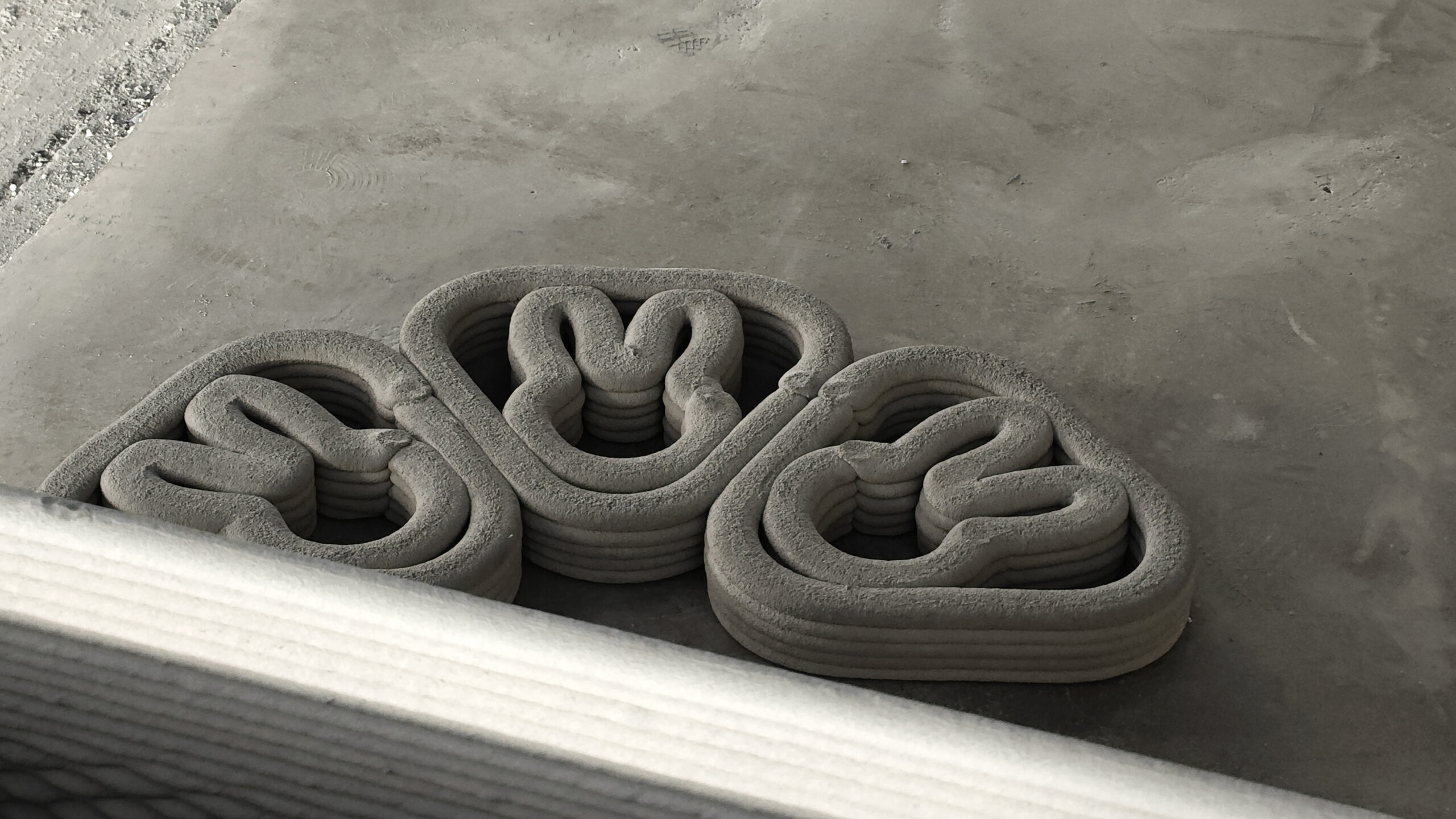
Some parts feature highly complex geometries that are difficult to produce using conventional manufacturing methods, prompting many engineers to immediately consider 3D printing as a solution. Nevertheless, a critical practical distinction must be made: being printable and being practically viable for 3D‑printing production are two entirely different matters. A complete feasibility‑evaluation workflow is required to bridge this gap. This article outlines design‑improvement strategies for complex components intended for 3D printing from four practical engineering perspectives: geometric structure, material selection, manufacturing process, and cost control. It equips engineering technicians to conduct objective solution assessments before committing production resources.
I. Why Complex Components Require Dedicated Feasibility Evaluation
The additive‑manufacturing industry often cites the claim that “geometric complexity incurs no additional costs”. Theoretically, compared with conventional processes such as milling and casting, 3D printing brings only moderate cost increases for highly complex geometries. Real‑world production, however, rarely matches this theoretical ideal.
Complex components frequently incorporate internal cavities, overhangs, thin‑wall features, multi‑material combinations, high‑precision mating surfaces, and other characteristics. Any of these features may trigger print failures or drive production costs far above expectations. Skipping evaluation before production may result in parts failing surface‑quality requirements and requiring extensive post‑processing work‑hours. In severe cases, residual‑stress‑induced cracking may render parts scrap and delay delivery of the full product assembly.
Feasibility evaluation is therefore not a perfunctory review step. It quantifies potential risks during the design phase and enables early design adjustments, so that the inherent advantages of 3D‑printing technology can be fully leveraged.
II. Four Core Dimensions of Feasibility Evaluation
1. Rationality Analysis of Geometric Structures
Part geometry is the primary criterion for judging whether 3D printing is practically achievable. The following structural features shall be reviewed item‑by‑item:
Overhang structures and overhang angles. Most metal 3D‑printing processes struggle with overhangs whose angles exceed 45°. For polymer‑printing processes such as FDM, support structures are generally mandatory for flat‑top overhangs with angles greater than 45°. Larger overhang areas increase support‑removal difficulty and degrade final surface quality. During evaluation, mark all overhang zones and calculate their area proportion. If the proportion exceeds 15%, structural optimization must be initiated.
Minimum wall thickness and fine‑feature dimensions. Each printing process imposes hard lower limits on formable wall thickness. For instance, SLM metal printing cannot stably produce walls thinner than 0.4 mm. Although SLA vat photopolymerization can achieve a Z‑axis layer thickness of 0.025 mm, the minimum printable feature in the XY plane is constrained by equipment spot size. During evaluation, compare every thin‑wall feature in drawings against the forming limits of the target process.
Internal cavities and closed flow channels. Fabricating enclosed cavities is a major advantage of 3D printing, yet it introduces challenges such as trapped powder/resin and poor inspectability of internal defects. Fully enclosed cavities trap residual powder and broken‑off‑support debris that cannot be cleared. Designs must therefore incorporate drain holes or adopt removable‑insert solutions. Mark all closed cavities during evaluation and verify whether feasible cleaning channels exist.
Assembly‑critical features. Threaded holes, bearing seats, sealing grooves and other mating features rarely meet assembly tolerances in their as‑printed state and require post‑machining allowances. Distinguish surfaces usable directly after printing from those requiring subsequent machining. For machined surfaces, reserve a machining allowance of 0.2–0.8 mm and ensure tool access for subsequent material removal.
2. Material Compatibility Assessment
Selected materials define the upper bound of mechanical performance and also govern print success rates and post‑processing workflows.
Prioritize print‑process compatibility before reviewing performance parameters. High‑strength alloys such as Inconel 718 and Ti‑6Al‑4V exhibit excellent material‑handbook properties yet suffer from susceptibility to cracking and high residual‑stress levels. Material selection should not rely solely on handbook mechanical data; real‑world defect records for the given material‑process combination shall be consulted. Even for a single alloy grade, stable‑process windows vary noticeably with powder batches and printer manufacturers.
Account for material anisotropy. In 3D‑printed parts, inter‑layer bonding (Z‑direction) typically delivers mechanical properties 10 %‑30 % inferior to those in the XY plane. For components subjected to multi‑axial loading, align the highest‑stress directions with the higher‑strength print plane using stress‑simulation outputs during evaluation. Adjust build orientation when necessary.
Match materials with heat‑treatment and post‑processing capabilities. Many high‑performance alloys require solution‑aging heat treatment to achieve target mechanical properties, yet heat treatment may induce distortion and dimensional shift. When selecting materials, concurrently validate the full post‑processing workflow: confirm furnace chamber dimensions and atmosphere compatibility, and verify that heat‑treatment‑induced deformation remains within allowable dimensional tolerances.
3. Manufacturing‑Process Matching
A single part can often be produced by multiple 3D‑printing technologies. Appropriate‑process selection directly determines final‑part success.
Match accuracy and surface‑roughness requirements to process capabilities. SLM metal printing typically yields Ra 6‑15 μm surface roughness, substantially coarser than the Ra 0.8 μm achievable by precision milling. Where key surfaces demand Ra ≤ 1.6 μm, post‑machining allowances are mandatory. SLA and DLP photopolymerization deliver Ra 0.4‑1.6 μm and are better suited for appearance‑focused parts and precision prototypes.
Match part dimensions to printer build‑chamber capacity. Maximum part dimensions must not exceed nominal build‑chamber limits. Additional space is consumed by baseplates, transition structures, and thermal effects; effective usable volume generally equals 85 %‑90 % of nominal chamber size. If a part exceeds single‑build limits, evaluate feasibility of splitting into sub‑components for separate printing followed by welding‑based assembly.
Identify economic‑batch thresholds. Unit‑cost for 3D‑printed parts rises nearly linearly with quantity, whereas conventional manufacturing benefits from mold‑cost amortization and decreasing per‑unit costs at higher volumes. For metal 3D printing, cost‑competitiveness versus conventional methods generally lies within batch sizes of 50‑200 units; polymer‑printing economic thresholds are lower. Clarify actual production volumes during evaluation to judge process‑economy viability.
4. Comprehensive Cost‑and‑Lead‑Time Accounting
Cost calculation shall not merely cover powder or filament consumption; all workflow phases must be included:
- Pre‑production: structural optimization, topological simulation, process simulation; 5‑40 engineering work‑hours depending on part complexity.
- Printing: equipment runtime, material consumption, support‑material overhead; protective‑gas costs for metal printing.
- Post‑processing: stress‑relief heat treatment, baseplate cutting, support removal, surface finishing, precision machining.
- Inspection: CT scanning, penetrant testing, coordinate‑measuring‑machine dimensional verification, mechanical‑specimen characterization.
A common misconception is estimating costs based solely on printing‑process expenditure while underestimating post‑processing expenses. In practice, post‑processing for complex metal components often accounts for 30 %‑50 % of total cost and may even exceed printing costs under certain operating conditions. Similarly, lead‑times are extended by furnace‑scheduling constraints and post‑processing‑queue delays.
III. Core Optimization Strategies in the Design Phase
After identifying risks via evaluation, optimization shall prioritize design modifications to circumvent process defects, rather than attempting to compensate solely through print‑parameter tuning.
Topology Optimization and Bionic‑Structure Design
Topology optimization removes low‑stress material volumes according to load‑conditions to generate lightweight, bionic‑branch‑like geometries inherently suited for 3D printing. Complexity is thereby converted into performance gains. Apply minimum‑feature‑size constraints consistent with printer capabilities. Smooth surfaces after optimization to mitigate stress concentrations at sharp corners.
Build‑Orientation Adjustment and Part‑Splitting Schemes
Build orientation directly influences overhang quantity, support volume, Z‑axis mechanical performance, build‑time, and surface quality. Optimize orientation to minimize support consumption, align high‑stress regions with the stronger XY print plane, and reduce large‑area overhangs. When a single orientation cannot satisfy all requirements, split the component into separately‑printed sub‑parts for subsequent assembly or joining. This approach frequently delivers lower overall cost than forcing monolithic printing.
Design Principles for Reducing Support Structures
Supports consume material, add manual‑removal labor, and risk part‑surface damage during removal. Minimize supports by: tilting overhang surfaces toward self‑supporting angles (approximately 45° for metal printing; down to 30° under select process conditions); adding chamfers to cavity bottoms; replacing solid overhangs with lattices. Where supports are unavoidable, design for tool‑access during removal; avoid supports trapped within enclosed volumes.
Residual‑Stress and Distortion Control
Layer‑by‑layer melting‑and‑cooling in metal printing generates high residual‑stress, potentially causing warpage or cracking. Mitigation measures include: baseplate preheating to reduce thermal gradients; partition‑scanning and layer‑rotation scan strategies; avoiding large continuous horizontal layers; adding fillets at thick‑to‑thin transitions. For high‑accuracy parts, thermo‑mechanical process simulation predicts distortion; pre‑compensate dimensions during design.
IV. Common Production Pitfalls
- Blind pursuit of excessive complexity. Greater complexity does not inherently equal superior performance. Artificially over‑complicated geometries raise print difficulty and complicate inspection‑and‑acceptance. Optimize for moderate complexity: deploy intricate structures only where performance benefits are justified, and simplify geometry elsewhere.
- Neglecting post‑processing accessibility. Designers often prioritize monolithic‑part aesthetics while overlooking manufacturability for downstream operators. Supports inside deep holes, burrs within cavities, and polishing‑access limitations inside enclosed volumes represent major delivery‑stage bottlenecks. Simulate tool reachability across all surfaces during design to avoid costly rework after production.
- Simulation decoupled from real‑world operating conditions. Process simulation delivers valuable insights, yet prediction accuracy depends on well‑calibrated material parameters, boundary conditions, and equipment settings. Generic simulation templates produce large deviations from physical outcomes. For critical components, fabricate small‑scale feature‑test specimens first, calibrate simulation models against measured data, then perform formal‑part evaluation.
V. Rapid Feasibility‑Evaluation Decision Matrix
The table below enables quick risk‑level identification and optimization‑priority assignment during design reviews.
| Evaluation Dimension | Low Risk (Proceed Directly) | Medium Risk (Proceed after Optimization) | High Risk (Revise Overall Concept) |
| Geometric‑overhang Fraction | < 10 %, predominantly self‑supporting | 10 %‑25 %, localized supports required | > 25 %, extensive overhangs with non‑removable supports |
| Minimum Wall Thickness | ≥ 2 × process minimum threshold | 1‑2 × process minimum threshold | At or below process‑forming limit |
| Material‑Process Compatibility | Mature material with well‑documented application‑defect history | Proven application cases yet narrow‑process window | Novel material without validated‑process data |
| Post‑Processing Feasibility | Standard workflow: stress‑relief + machining | Specialized heat‑treatment or complex surface finishing required | Internal cavities uncleanable; internal features non‑inspectable |
| Cost Economy | Cost comparable‑to‑or‑lower‑than conventional alternatives | Cost 10 %‑30 % higher, offset by measurable performance gains | Cost > 50 % higher with no clear performance benefit |
Usage Notes: Assess each dimension independently. The overall risk level corresponds to the highest‑risk individual dimension. High‑risk ratings require fundamental design revisions; medium‑risk ratings call for iterative optimization; low‑risk ratings permit advancement to detailed‑design activities.
VI. Practical Implementation Recommendations
- Build internal corporate‑process databases. Record process parameters, observed defects, post‑processing workflows, and final‑part outcomes for every print (success or failure). Internal defect‑and‑parameter libraries reduce uncertainty for future projects.
- Prioritize specimen validation. For critical complex components, produce scaled‑down parts or feature‑test specimens before full‑scale production to validate high‑risk aspects such as cavity‑forming behavior or new‑material cracking propensity. Specimen‑testing costs are far lower than full‑part scrap losses.
- Cross‑functional joint reviews. Feasibility evaluation shall not rest solely with design engineers. Print‑process engineers, post‑processing technicians, and quality‑inspection staff shall participate, providing perspectives covering manufacturing, finishing, and inspection. Many design flaws become visible only from a post‑processing viewpoint.
The true value of 3D printing lies not in its ability to produce arbitrary shapes, but in knowing which parts are well‑suited for it. Feasibility evaluation for complex components essentially balances design freedom against real‑world manufacturing capacity. By conducting evaluation early and implementing design improvements, complex‑part manufacturing transitions from trial‑and‑error experimentation to a controlled, actionable engineering practice.